CCNA Practice: VLANs and Subnetting
This is the first of several lab walkthroughs I will post documenting my preparation for the CCNA exam later this year. At first, I planned on including this entire lab in one post, but as it covers a wide variety of exam topics, I decided to break it up into parts. For this first part, I am going to break up my network into subnets with corresponding VLANs. Let’s get started!
-
1. What is a VLAN?
A VLAN stands for a virtual local area network. Basically, VLANs allow a network administrator to break up an existing physical LAN into multiple logical LANs to improve the security, manageability, and efficiency of a network. Here’s a simple example. Let’s say I have an office building with four floors. Each floor is home to a different team within the organization: customer service reps, salespeople, the IT team, and the company executives on the top floor. If I keep all those teams on the same LAN, that means that all those teams are also on the same broadcast domain. This means that broadcast traffic like ARP requests are going to generate a lot of noise and could noticeably slow down the network in some cases. It also means that managing access to network resources will be more cumbersome for a network administrator, because traffic between certain hosts on the IT floor, for example, may need to be off-limits for hosts on the customer service floor. By segmenting the network into separate VLANs, a network administrator can isolate traffic within those VLANs, thereby adding a layer of security to protect network traffic and also dividing the broadcast domain to mitigate network congestion.
-
2. Topology
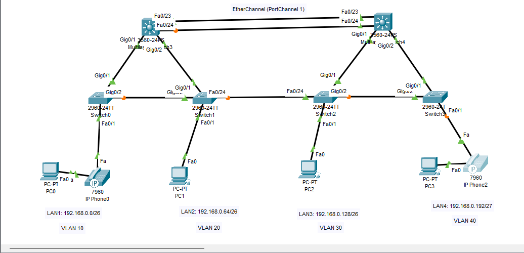
The image above is taken from my packet tracer file where I have begun constructing the access and distribution layers of my network topology. Eventually I will add more hosts to the access layer and routers in the distribution and core layers, but for now, I want to set up my VLANs. As you can see, my topology consists of 4 VLANs, but I am also going to need a separate VLAN for voice over IP traffic, a management VLAN to manage my network devices, and a native VLAN to carry any traffic that does not have a VLAN tag. Here’s what that looks like:
- VLAN 10: Customer Service
- VLAN 20: Sales
- VLAN 30: IT
- VLAN 40: Executives
- VLAN 88: Management
- VLAN 99: Native
But, before I begin to configure the VLANs, I need to make sure my IP addressing and subnetting scheme is ready to go as well.
-
3. Subnetting the network
Once VLANs are configured on my LAN, the data link layer of my network is segmented, but what about the network layer? What if I need to route IP packets to each network segment? Let me take this opportunity to explain IPv4 subnetting. My network is 192.168.0.0/24. That /24 on the end means that the first 24 bits (or the first three octets) represent the network of the IP address. The remaining 8 bits represent the host within that network. Those 8 bits have 256 possible combinations. Two of those combinations (the first possible one and the last possible one) represent the network and broadcast addresses respectively. That means I have a total of 254 usable addresses left within this network.
Now, if I want to divide that network based on the four floors of the office building in my earlier example, I need to divide 192.168.0.0/24 into five subnets. Four of those subnets will be used now, and the fifth is for device management which will be implemented later. Let’s say customer service, sales, and IT all need at least 50 usable hosts on their network. The executive LAN only needs 20, and the management network only needs 30. Remember that there are 256 combinations in the 8 host bits of my network address. All I need to do now is divide those 256 possibilities into segments or ‘subnets.’
For example, my first subnet, customer service, needs 50 hosts. So, could I do 192.168.0.0 through 192.168.0.50 as my first subnet? No. I must consider that the network can only be divided at the bit level, such as /24. So, what if I try /25? That would give me 192.168.0.0 through 192.168.0.128, but that doesn’t give me enough leftover space after .128 for my other four networks. Ok, then why not /27? Well, 192.168.0.0 through 192.168.0.32 would give me less than the 50 addresses I need for this subnet. The sweet spot here seems to be 192.168.0.0/26 for my first subnet, which would give me usable addresses 192.168.0.1 through 192.168.0.62. If you’re reading this and you’re new to subnetting, don’t worry. I know it’s confusing at first, but if you write out your addresses in binary and decimal form, analyzing the network and host bits as you go, it will quickly make sense.
So, let me subnet the rest of my network.
- LAN1(Customer Service): 192.168.0.0/26
- LAN2(Sales): 192.168.0.64/26
- LAN3(IT): 192.168.0.128/26
- LAN4(Executive): 192.168.0.192/27
- ExtraLAN(Management): 192.168.0.224/27
Now that I have that out of the way. I can get started configuring my network switches with VLANs.
-
4. Creating VLANs, Access and Trunk Ports
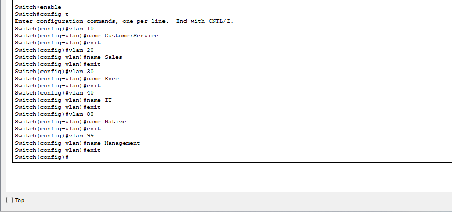
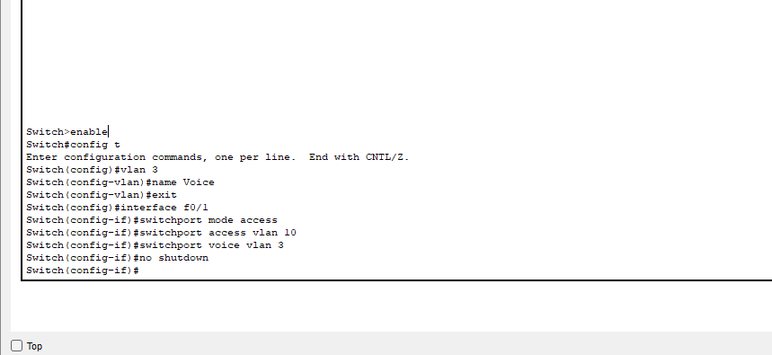
The first thing I need to do is create my VLANs on each switch in my LAN with the commands in the image above. My layer 2 switches are all Cisco 2960s, and the process for creating VLANs is simple. I just need to enter the VLAN number and then name the VLAN. Once the VLANs have been created for each switch, I need to configure access ports. An access port is configured to belong to a particular VLAN, so whatever host connects to that switchport belongs to the VLAN configured. Additionally, if Voice over IP is being used on the switchport, that belongs to a separate VLAN and must also be configured on the switchport.
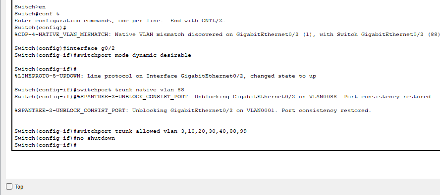
Now that all my VLANs have been created and can access the switches, I need to create trunk links so that all my VLANs can travel between switches. A trunk port is designed to carry all allowed VLAN traffic unlike an access port which is designed for one specific VLAN in addition to a voice VLAN. To configure trunk ports, I also need to specify the trunk negotiation between switches. For a trunk port to form, switches use dynamic trunking protocol to negotiate a trunk link. There are three modes a trunk port using DTP can be in: trunk, auto, or desirable. Basically, a port can be configured to actively try to create a link, passively accept a link if the connected port initiates a trunk or be statically configured as trunk ports in ‘trunk’ mode. For this scenario, I am going to configure my trunk ports in ‘desirable’ mode so that they can negotiate a link.
-
5. Creating SVI Default Gateways
The last thing I want to do in this lab is to configure my subnetting address scheme. Right now, I have four subnets to configure (I’m not going to configure the management interfaces just yet). Those four subnets need four separate default gateways, but they are sharing two layer 3 switches to route their traffic to remote networks. So, I am going to configure four virtual interfaces on the switch, which will be configured to serve as default gateways for their respective subnets. You can see the two switch virtual interfaces in one of my switch’s IP interface summary below.
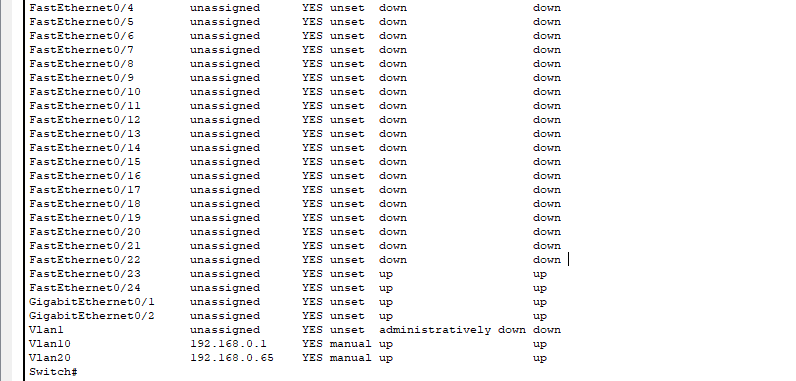
To make sure this is working, the PC connected to LAN2 or VLAN 20 has been given an IP address of 192.168.0.70/26, and should therefore be able to ping its default gateway, which is the SVI I just created on my layer 3 switch.

It works! Now, my network is segmented like I want. The subnets and VLANs are not able to communicate with each other just yet, but I will be covering inter-VLAN routing in my next post along with configuring Etherchannel to add some redundancy to my network, so stay tuned!